In this section Rangkaian Sirkuit pengatur volume digital discussed a series of digital volume control that is used in the amplifier or control.memang tone on tone, volume control is available but we can raise the volume control with this tesendiri.rangkaian circuit using IC DS1669 Digital Pot type-specific IC This volume.rangkaian settings are suitable for middle-class amplifier that small defenseless under 50 watts. To get a picture or a clear scheme of this circuit click on the image sequence
list of componen : Part Total Qty. Description Substitutions C1 1 0.1uf Ceramic Disc Capacitor U1 1 DS1669 Digital Pot IC (See Notes) S1, S2 2 Momentary Push Button Switch MISC 1 Board, Wire, Socket For U1.
Rangkaian FM TRANSMITTER - Skema rangkaian: Part Total Qty. Description Substitutions C1 1 0.001uf Disc Capacitor C2 1 5.6pf Disc Capacitor C3,C4 2 10uf Electrolytic Capacitor C5 1 3-18pf Adjustable Cap R1 1 270 Ohm 1/8W Resistor 270 Ohm 1/4W Resistor R2,R5,R6 3 4.7k 1/8W Resistor 4.7K 1/4W Resistor R3 1 10k 1/8W Resistor 10K 1/4W Resistor R4 1 100k 1/8W Resistor 100K 1/4W Resistor Q1, Q2 2 2N2222A NPN Transistor 2N3904 L1, L2 2 5 Turn Air Core Coil MIC 1 Electret Microphone MISC 1 9V Battery Snap, PC Board, Wire For Antenna

Skema Inverter dc 12v-120 volt ac circuit

Detail componen list:
Part Total Qty. Description Substitutions C1, C2 2 68 uf, 25 V Tantalum Capacitor R1, R2 2 10 Ohm, 5 Watt Resistor R3, R4 2 180 Ohm, 1 Watt Resistor D1, D2 2 HEP 154 Silicon Diode Q1, Q2 2 2N3055 NPN Transistor (see "Notes") T1 1 24V, Center Tapped Transformer (see "Notes") MISC 1 Wire, Case, Receptical (For Output]
Q1, q2, and t1 pad size effect watts generated, you can use larger transistors to obtain greater power as well as also for the transformer. here t1 uses 15 ampere, with this circuit generated 300 watts of power. to change the output voltage can be wrapped around your own secondary coil t1, multiply voltage windings for greater. install a fuse on the output to see the details look pengaman
Skema Sirkuit amplifier Lengkap- an amplifier / power amplifier circuit is 50 watts rms, which uses a transistor amplifier of npn and pnp 2n 3055 and 7391 which have 2n considerable power. Will be presented and links to sites that provide tutorials and free electronic circuit. To get a clear picture of this circuit click on the image sequenceComponen list for Amplifier : Part Total Qty. Description Substitutions R1 1 200 Ohm 1/4 W Resistor R2 1 200K 1/4 W Resistor R3 1 30K 1/4 W Resistor R5 1 1K 1/4 W Resistor R6 1 5K 1/4 W Resistor R7,R10 2 1 Meg (5%) 1/2 W Resistor R8,R9 2 0.4 Ohm 5 W Resistor R11 1 10K Pot R12,R13 2 51K 1/4 W Resistor R14 1 47K 1/4 W Resistor C1 1 100uF 35V Electrolytic Capacitor C2 1 0.011uF Capacitor C3 1 3750pF Capacitor C4,C6 2 1000pF Capacitor C5,C7,C8 3 0.001uF Capacitor C9 1 50pF Capacitor C10 1 0.3uF Capacitor C11,C12 2 10,000uF 50V Electrolytic Capacitor U1,U2 2 741 Op Amp U3 1 ICL8063 Audio Amp Transister Driver thingy Q1 1 2N3055 NPN Power Transistor Q2 1 2N3791 PNP Power Transistor BR1 1 250 V 6 Amp Bridge Rectifier T1 1 50V Center Tapped 5 Amp Transformer S1 1 SPST 3 Amp Switch S2 1 DPDT Switch F1 1 2 Amp Fuse SPKR1 1 8 Ohm 50W Speaker MISC 1 Case, Knobs, Line Cord, Binding Posts Or Phono Plugs (For Input And Output), Heatsinks For Q1 And Q2
Rangkaian Sirkuit tone control- Preamplifier is basically the most used in sound quality but it also needs the support of tone controls and tone control amplifier.nah we present here are included in standard sizes kwalitasnya, please try your own.


List of component of rangkaian sirkuit Tone control : Part Total Qty. Description Substitutions C1, C3, C5, C7, C15, C16 6 2.2uf Electrolytic Capacitor C2, C6 2 0.05uF Ceramic Disc Capacitor C4 1 0.22uF Disc Capacitor C8, C10 2 0.015uF Ceramic Disc Capacitor C9 1 100uF Electrolytic Capacitor C11, C12, C13, C14 4 0.1uF Ceramic Disc Capacitor R1, R4 2 10K 1/4W Resistor R2, R5 2 33K 1/4W Resistor R3, R6 2 4.7K 1/4W Resistor R7 1 2.2K 1/4W Resistor R8, R9, R10, R11 4 50K Linear Pot U1 1 TDA1524A Tone Control IC S1 1 SPST Switch J1, J2, J3, J4 4 RCA Jacks Other connectors of your choice MISC 1 Board, Wire, Knobs, 18 Pin Socket
Rangkaian preamphead/head preamplifier
One of the elements to produce a good sound dlm preamphead.karena tape player is an early head preamp audio processing is taken by the head.

The componen needed:
R1 = R5 = 56k C2 = C6 = 1,5nF R2 = R6 = 2,2M C3 = C7 = 22uF/10V R3 = R7 = 270 ohm C4 = C8 = 1uF/25V R4 = R8 = 330k C9 = C10 = 4,7uF/25V R9 = R10 = 100k IC = LM387
Video fans and professionals in the field will find in this small signal distributor-amplifier an excellent ally when it’s necessary to distribute a single video signal across several equipments. The circuit shown here should have a lot of applications.

Basically, the distribution amplifier takes thecomposite video signal from a video player (VCR) or a video generator (analogue output) and buffers it in such a way that it can be simultaneously applied to up to five different video equipment inputs, like monitors, TV sets, other VCRs and so on. For example, in a hall, the image produced by a central DVD player can be shown on five different TV screens with the sound reproduced through a separate amplifier.


The circuit is based on the type EL2020 (or similar) operational amplifier which is marled by large bandwidth. The LL2020 amplifies the video signal applied to the input stage, with a gain adjustment range of ±6 dB. Output transistor Q1, a 2N3866, applies the video signal to the five outputs designed to drive loads with 75-Ω impedance.


The circuit requires a ±12 V symmetrical supply voltage, which can be obtained from aconventional power supply as shown by the schematic.

How To Choose The Right Car Subwoofer

How To Choose The Right Car Subwoofer-The Bottom Line Read this review to find out how to choose the right subwoofer(s) for your car.

Choosing a subwoofer can be a very difficult but interesting task. When you're choosing a car sub, you need to know what you really want. It depends what kind of music you listen to, and other factors.

-Your Car Is Not A House-
*I have heard subwoofers in big rooms in houses. The subs for example were 8", and the rooms were large. The bass was terrible because it wasn't able to fill the room or anything. The vibrations and everything that the sub had to do was not there. The car is a completely different environment. Bazooka makes popular subs, and a lot of people buy their 8" amplified tubes, I have heard these tubes in Jeep Wranglers and in a lot of SUVs, they can make the cars shake and vibrate, and get people to stare. Car subwoofers can also be as small as 6.5"... So as you can see, the bass reflects of more areas in a car, thus giving a drastically improved bass response because the smaller area. So you don't need to get a 10" or 12" neccassarily to get your car to vibrate.

-Tubes VS. Box Enclosures-
*Tubes - The only brand that makes tubes is Bazooka. Many of the tubes have built-in amplifiers, they are easy to move, and they are quite inexpensive. They are popular because of their simplicity and price. These will create bass, but not the cleanest or lowest hitting bass out there. So if you're into music, then these aren't for you. If you want something to just pound, then these are quite good. However, you can do better with box enclosures.

*Box Enclosures - Box enclosures are when you buy either a ported or sealed enclosure, and put in however many drivers the box can hold. You can get one that holds either one, two, or three. Many people uses sealed enclosures because they are the smaller one of the two, but I use a ported in my car. Unlike tubes, with boxes, you can add whichever brand of woofers you want, and your own amplifier. However, this can be a more difficult task than just putting in a tube. But, you get much more versatility. Whether you're setting up a budget or audiophile sub hook-up, a majority of the people will use box enclosures.

-The Different Materials-
*Different subwoofers are made out of different materials. Many of the more inexpensive and common subs are built out of paper cones. These will generally handle the job well, but there will be more distortion, but the price difference is quite large. Polypropylene is becoming quite of a popular polymer, it is higher quality than paper, and still quite inexpensive. The best of the new subwoofers are alluminum subs. I use a single alluminum Audiobahn 12" in my Pathfinder off of a Kicker amp, and I love it. The sound quality that it gives me is very clean and smooth. The surrounds around the voice coils are usually rubber. Other brands may use other types of surrounds, but rubber is still the most commonly used and most durable.

-Voice Coils-
*The more layers and space that you have, the better sound quality you get. There are two kinds of bass, clean bass and "ghetto bass". Clean bass subs include brands such as Nakamichi, McIntosh, Blaupunkt, Audiobahn, Infinity, and other higher end brands. They usually have dual-voice coils and give very clean bass. There are also such things as "ghetto subs" which can handle enormous amounts of power, such as 1000 Watt+ RMS, but their bass is very dirty and distorted, it's not good for real music. I've seen very expensive subs that have quadruple voice coils (Sony Mobile ES), but a majority of the high quality subs will have dual-voice coils, but you can definitly do with one.

-Driver Sizes-
*Well, as you can see, in the car an 8" sub will make the car vibrate and do everything that someone would want a subwoofer to do. However, the larger the subwoofer, it can get: Louder, cleaner, hit lower frequencies, and handle more power. If you've got a tight budget, an 8" will do the job, but if you're an audiophile or are really into music, then bass is would be very important to you. I think the ideal size for any subwoofer is 12" because it can hit the lowest notes without using all that much power. A 12" can certainly reach lower notes than an 8". If you can hear the difference in frequencies or need that "bang", then you should get a larger subwoofer. However, if you just want to fill in some lower notes but aren't expecting that much, then go for a 8" subwoofer or something like that. It would save you money.

-Amps and Power-
*The power of your amp should depend on the size of the driver or how much bass you want. I use a fairly powerful amp to power my Audiobahn. I know people that are car stereo crazy, and they power over 1000 Watts to some of their subs, but that is over-kill. It can break the glass on a car, and if the subwoofer is poorer quality, there is a huge amount of distortion. You should never exceed the RMS rating on your drivers, because one day your sub will go "pop!", and there will be nothing left. I think something around 200 Watts per driver should be enough for most people. Most amps that have much more power than that are over-kill I think.

-In Conclusion-
*I hope that this review has helped you in finding the perfect subwoofer for your car. If you have trouble finding the right brand or anything, just look up consumer reviews or get advice from friends. My personal advice is that Audiobahn or Blaupunkt are both superb brands and you'll definitely get a lot for your money. But, most brands will make consumers happy. well, good luck!
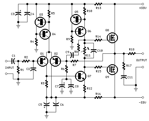
this is 25 Watt MosFet Audio Amplifier page, is by far the most visited of this site, and is on-line since March 1999. The circuit has been built by many amateurs all around the world and is still very popular: as a logical consequence, in these years this small amplifier was frequently debated in Audio forums and rumors arose about its quiescent current stability and other topics.
Eventfully, I was now able to get and carry to my laboratory one of the first prototypes of the complete Stereo Amplifier I built in 1992 for a friend, so I was very anxious to perform extended tests on this amplifier after 15 years of use.
The tests results, with some added comments are shown below.
High Quality simple design Schema 25 Watt MosFet Audio Amplifier
No need for a preamplifier-# Can be directly connected to CD players, tuners and tape recorders. Simply add a 10K Log potentiometer (dual gang for stereo) and a switch to cope with the various sources you need.
# Q6 & Q7 must have a small U-shaped heatsink.
# Q8 & Q9 must be mounted on heatsink.
# Adjust R11 to set quiescent current at 100mA (best measured with an Avo-meter connected in series to Q8 Drain) with no input signal.
# A correct grounding is very important to eliminate hum and ground loops. Connect to the same point the ground sides of R1, R4, R9, C3 to C8. Connect C11 to output ground. Then connect separately the input and output grounds to power supply ground.
# An earlier prototype of this amplifier was recently inspected and tested again after 15 years of use. Schema 25 Watt
R1,R4_________47K 1/4W Resistors
R2____________4K7 1/4W Resistor
R3____________1K5 1/4W Resistor
R5__________390R 1/4W Resistor
R6__________470R 1/4W Resistor
R7___________33K 1/4W Resistor
R8__________150K 1/4W Resistor
R9___________15K 1/4W Resistor
R10__________27R 1/4W Resistor
R11_________500R 1/2W Trimmer Cermet
R12,R13,R16__10R 1/4W Resistors
R14,R15_____220R 1/4W Resistors
R17___________8R2 2W Resistor
R18____________R22 4W Resistor (wirewound)

C1___________470nF 63V Polyester Capacitor
C2___________330pF 63V Polystyrene Capacitor
C3,C5________470µF 63V Electrolytic Capacitors
C4,C6,C8,C11_100nF 63V Polyester Capacitors
C7___________100µF 25V Electrolytic Capacitor
C9____________10pF 63V Polystyrene Capacitor
C10____________1µF 63V Polyester Capacitor

Q1-Q5______BC560C 45V 100mA Low noise High gain PNP Transistors
Q6_________BD140 80V 1.5A PNP Transistor
Q7_________BD139 80V 1.5A NPN Transistor
Q8_________IRF530 100V 14A N-Channel Hexfet Transistor
Q9_________IRF9530 100V 12A P-Channel Hexfet Transistor

Power supply circuit diagram:
Power supply
Parts:

R1____________3K3 1/2W Resistor

C1___________10nF 1000V Polyester Capacitor
C2,C3______4700µF 50V Electrolytic Capacitors
C4,C5_______100nF 63V Polyester Capacitors

D1__________200V 8A Diode bridge
D2__________5mm. Red LED

F1,F2_______3.15A Fuses with sockets

T1__________220V Primary, 25 + 25V Secondary 120VA Mains transformer

PL1_________Male Mains plug

SW1_________SPST Mains switch
Useful Schema 18W Audio AmplifierDiagram
Schema 18W Audio

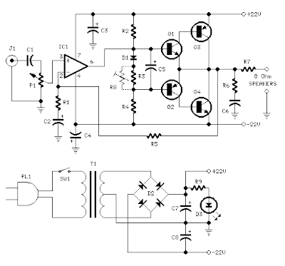
Circuit diagram:
18 Watt Amplifier
Amplifier parts:

P1_____________22K Log. Potentiometer (Dual-gang for stereo)

R1______________1K 1/4W Resistor
R2______________4K7 1/4W Resistor
R3____________100R 1/4W Resistor
R4______________4K7 1/4W Resistor
R5_____________82K 1/4W Resistor
R6_____________10R 1/2W Resistor
R7_______________R22 4W Resistor (wirewound)
R8______________1K 1/2W Trimmer Cermet (optional)

C1____________470nF 63V Polyester Capacitor
C2,C5_________100µF 3V Tantalum bead Capacitors
C3,C4_________470µF 25V Electrolytic Capacitors
C6____________100nF 63V Polyester Capacitor

D1___________1N4148 75V 150mA Diode

IC1________TLE2141C Low noise, high voltage, high slew-rate Op-amp

Q1____________BC182 50V 100mA NPN Transistor
Q2____________BC212 50V 100mA PNP Transistor
Q3___________TIP42A 60V 6A PNP Transistor
Q4___________TIP41A 60V 6A NPN Transistor

J1______________RCA audio input socket

Power supply parts:

R9______________2K2 1/4W Resistor

C7,C8________4700µF 25V Electrolytic Capacitors

D2_____________100V 4A Diode bridge
D3_____________5mm. Red LED

T1_____________220V Primary, 15 + 15V Secondary, 50VA Mains transformer

PL1____________Male Mains plug

SW1____________SPST Mains switch

* Can be directly connected to CD players, tuners and tape recorders.
* Do not exceed 23 + 23V supply.
* Q3 and Q4 must be mounted on heatsink.
* D1 must be in thermal contact with Q1.
* Quiescent current (best measured with an Avo-meter in series with Q3 Emitter) is not critical.
* Adjust R3 to read a current between 20 to 30 mA with no input signal.
* To facilitate quiescent current setting add R8 (optional).
* A correct grounding is very important to eliminate hum and ground loops. Connect to the same point the ground sides of J1, P1, C2, C3 & C4. Connect C6 to the output ground.
* Then connect separately the input and output grounds to the power supply ground.

Technical data:

Output power:
18 Watt RMS into 8 Ohm (1KHz sine wave)
Sensitivity:
150mV input for 18W output
Frequency response:
30Hz to 20KHz -1dB
Total harmonic distortion @ 1KHz:
0.1W 0.02% 1W 0.01% 5W 0.01% 10W 0.03%
Total harmonic distortion @10KHz:
0.1W 0.04% 1W 0.05% 5W 0.06% 10W 0.15%
Unconditionally stable on capacitive loads
Description68uF 400V High Ripple Capacitor

68uF 400V High Ripple Capacitor.\n\n105 Degrees C, 4uA Leakage. 16mm x 32mm \n\n As used in Switched-Mode Power Supplies. Ballast Capacitors, etc. 105 Degrees C. see pictures :

Capacitor discharge of latching relays and rotary filter - Direct current circuitry for sequentially energizing two or more motors or ther load devices, using capacitive discharge to latch in a relay for each load device. During one stage of operation a relatively small voltage is impressed on one lead of a capacitor whose other lead is grounded; a charge is thereby developed in the capacitor. Subsequently a relatively large voltage is impressed on the other lead of the capacitor to direct the charge into the coil of the relay, thereby effecting a relay latching action. The capacitor thereafter isolates the latching circuit from a de-latching circuit; the de-latching circuit is part of a latching circuit for a second relay used to energize a second load device. The invention is particularly useful in sequentially operating electric motors used in self-cleaning engine air cleaners. see full archive at http://www.freepatentsonline.com/4009011.html
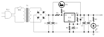
Skema Regulated Power Supply Circuit diagram- This is A very good and powerful Regulated Power Supply section was implemented by simply adding a PNP power transistor to the excellent LM317T adjustable regulator chip. In this way this circuit was able to deliver much more than the power required to drive two Mini-MosFet amplifiers to full output (at least 2Amp @ 40V into 4 Ohm load) without any appreciable effort.

Notes:

  • Q2 and Q3 in the Power Amplifier must be mounted each on a finned heatsink of at least 80x40x25mm.
  • Q1 and IC1 in the Regulated Power Supply must be mounted on a finned heatsink of at least 45x40x17mm.
  • A power Transformer having a secondary winding rated at 35 - 36V and 50VA (i.e. about 1.4Amp) is required if you intend to use Loudspeaker cabinets of 8 Ohm nominal impedance. To drive 4 Ohm loads at high power levels, a 70 - 75VA Transformer (2Amp at least) will be a better choice. These transformers are usually center tapped: the central lead will be obviously left open.
  • For the stereo version of this project, R16 and C11 in the Preamp will be in common to both channels: therefore, only one item each is necessary. In this case, R16 must be a 1K5 1/2W resistor. The value of C11 will remain unchanged
Mini Preamp Circuit diagram- The Preamp sensitivity and overload margin were designed to cope with most modern music programme sources like CD players, Tape recorders, iPods, Computer audio outputs, Tuners etc. The source selecting switches and input connectors are not shown and their number and arrangement are left to the constructor's choice.
To obtain a very high input overload margin, the volume control was placed at the preamp input. After a unity gain, impedance converter stage (Q1) a negative-feedback Baxandall-type Bass and Treble tone control stage was added. As this stage must provide some gain (about 5.6 times) a very low noise, "bootstrapped" two-transistors circuitry with FET-input was implemented. This stage features also excellent THD figures up to 4V RMS output and a low output impedance, necessary to drive properly the Mini-MosFet Power Amplifier, but can also be used for other purposes.Preamp Parts:

P1______________50K Log. Potentiometer (or 47K)
(twin concentric-spindle dual gang for stereo)
P2,P3__________100K Linear Potentiometers
(twin concentric-spindle dual gang for stereo)

R1_____________220K 1/4W Resistor
R2_____________100K 1/4W Resistor
R3_______________2K7 1/4W Resistor
R4,R5____________8K2 1/4W Resistors
R6_______________4K7 1/4W Resistor
R7,R8,R13________2K2 1/4W Resistors
R9_______________2M2 1/4W Resistor
R10,R11_________47K 1/4W Resistor
R12_____________33K 1/4W Resistor
R14____________470R 1/4W Resistor
R15_____________10K 1/4W Resistor
R16______________3K3 1/4W Resistor (See Notes)

C1,C2,C9_______470nF 63V Polyester Capacitors
C3,C4___________47nF 63V Polyester Capacitors
C5,C6____________6n8 63V Polyester Capacitors
C7______________10µF 63V Electrolytic Capacitor
C8,C10__________22µF 25V Electrolytic Capacitors
C11____________470µF 25V Electrolytic Capacitor (See Notes)

Q1,Q3_________BC550C 45V 100mA Low noise High gain NPN Transistors
Q2___________2N3819 General-purpose N-Channel FET
Power Amplifier Circuit diagram-This project was a sort of challenge: designing an audio amplifier capable of delivering a decent output power with a minimum parts count, without sacrificing quality.Power Amplifier Circuit diagram

The Power Amplifier section employs only three transistors and a handful of resistors and capacitors in a shunt feedback configuration but can deliver more than 18W into 8 Ohm with <0.08%>

Setting up the Power Amplifier:

The setup of this amplifier must be done carefully and with no haste:

  1. Connect the Power Supply Unit (previously tested separately) to the Power Amplifier but not the Preamp: the input of the Power Amplifier must be left open.
  2. Rotate the cursor of R4 fully towards Q1 Collector.
  3. Set the cursor of R3 to about the middle of its travel.
  4. Connect a suitable loudspeaker or a 8 Ohm 20W resistor to the amplifier output.
  5. Connect a Multimeter, set to measure about 50V fsd, across the positive end of C5 and the negative ground.
  6. Switch on the supply and rotate R3 very slowly in order to read about 23V on the Multimeter display.
  7. Switch off the supply, disconnect the Multimeter and reconnect it, set to measure at least 1Amp fsd, in series to the positive supply (the possible use of a second Multimeter in this place will be very welcomed).
  8. Switch on the supply and rotate R4 very slowly until a reading of about 120mA is displayed.
  9. Check again the voltage at the positive end of C5 and readjust R3 if necessary.
  10. If R3 was readjusted, R4 will surely require some readjustment.
  11. Wait about 15 minutes, watch if the current is varying and readjust if necessary.
  12. Please note that R3 and R4 are very sensitive: very small movements will cause rather high voltage or current variations, so be careful.
  13. Those lucky enough to reach an oscilloscope and a 1KHz sine wave generator, can drive the amplifier to the maximum output power and adjust R3 in order to obtain a symmetrical clipping of the sine wave displayed.
Car Subwoofer Driver Diagram- Circuit description:

The stereo signals coming from the line outputs of the car radio amplifier are mixed at the input and, after the Level Control, the signal enters the buffer IC1A and can be phase reversed by means of SW1. This control can be useful to allow the subwoofer to be in phase with the loudspeakers of the existing car radio.
Then, a 12dB/octave variable frequency Low Pass filter built around IC1B, Q1 and related components follows, allowing to adjust precisely the low pass frequency from 70 to 150Hz.
Q2, R17 and C9 form a simple dc voltage stabilizer for the input and filter circuitry, useful to avoid positive rail interaction from the power amplifier to low level sections.

Notes:

  • IC2 must be mounted on a suitable finned heatsink
  • Due to the long time constant set by R17 and C9 in the dc voltage stabilizer, the whole amplifier will become fully operative about 15 - 30 sec. after switch-on.

Technical data:

Output power (1KHz sinewave):
22W RMS into 4 Ohms at 14.4V supply
Sensitivity:
250mV input for full output
Frequency response:
20Hz to 70Hz -3dB with the cursor of P2 fully rotated towards R12
20Hz to 150Hz -3dB with the cursor of P2 fully rotated towards R11
Total harmonic distortion:
17W RMS: 0.5% 22W RMS: 10%
My Zimbio
> TopOfBlogs .sg   TopOfBlogs